blog
Multi-Cloud Deployment for MariaDB Replication Using WireGuard

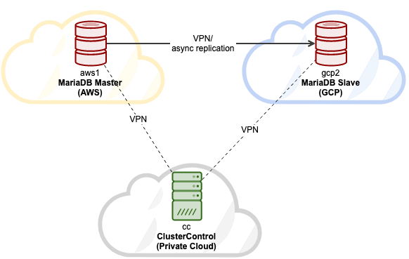
In this blog post, we are going to look into how to deploy a MariaDB replication setup in a multi-cloud environment. Suppose our primary application is located at AWS, it’s the best idea to set up AWS as the primary datacenter hosting the MariaDB master. The MariaDB slave will be hosted on GCP and ClusterControl is located inside the company’s private cloud infrastructure in the office. They are all connected via WireGuard simple and secure VPN tunnel in the IP range of 192.168.50.0/24. ClusterControl will use this VPN interface to perform deployment, management and monitoring on all database nodes remotely.
Here are our hosts:
- Amazon Web Service (AWS):
- Host: MariaDB master
- Public IP: 54.151.183.93
- Private IP: 10.15.3.170/24 (VPC)
- VPN IP: 192.168.50.101
- OS: Ubuntu 18.04.4 LTS (Bionic)
- Spec: t2.medium (2 vCPU, 4 GB memory)
- Google Cloud Platform (GCP):
- Host: MariaDB slave
- Public IP: 35.247.147.95
- Private IP: 10.148.0.9/32
- VPN IP: 192.168.50.102
- OS: Ubuntu 18.04.4 LTS (Bionic)
- Spec: n1-standard-1 (1 vCPU, 3.75 GB memory)
- VMware Private Cloud (Office):
- Host: ClusterControl
- Public IP: 3.25.96.229
- Private IP: 192.168.55.138/24
- VPN IP: 192.168.50.100
- OS: Ubuntu 18.04.4 LTS (Bionic)
- Spec: Private cloud VMWare (2 CPU, 2 GB of RAM)
Our final architecture will be looking something like this:
The host mapping under /etc/hosts on all nodes is:
3.25.96.229     cc clustercontrol office.mydomain.com
54.151.183.93   aws1 db1 mariadb1 db1.mydomain.com
35.247.147.95   gcp2 db2 mariadb2 db2.mydomain.com
Setting up host mapping will simplify our name resolving management between hosts, where we will use the hostname instead of IP address when configuring Wireguard peers.
Installing WireGuard for VPN
Since all servers are in three different places, which are only connected via public network, we are going to set up VPN tunneling between all nodes using Wireguard. We will add a new network interface on every node for this communication with the following internal IP configuration:
- 192.168.50.100 – ClusterControl (Office private cloud)
- 192.168.50.101 – MariaDB master (AWS)
- 192.168.50.102 – MariaDB slave (GCP)
Install Wireguard as shown in this page on all three nodes:
$ sudo add-apt-repository ppa:wireguard/wireguard
$ sudo apt-get upgrade
$ sudo apt-get install wireguard
For Ubuntu hosts, just accept the default value if prompted during the wireguard installation. Note that it’s very important to upgrade the OS to the latest version for wireguard to work.
Reboot the host to load the Wireguard kernel module:
$ rebootOnce up, configure our host mapping inside /etc/hosts on all nodes to something like this:
$ cat /etc/hosts
3.25.96.229     cc clustercontrol office.mydomain.com
54.151.183.93   aws1 db1 mariadb1 db1.mydomain.com
35.247.147.95   gcp2 db2 mariadb2 db2.mydomain.com
127.0.0.1       localhost
Setting up Wireguard
** All steps under this section should be performed on all nodes, unless specified otherwise.
1) On all nodes as a root user, generate a private key and assign a secure permission
$ umask 077
$ wg genkey > /root/private
2) Then, add a new interface called wg0:
$ ip link add wg0 type wireguard3) Add the corresponding IP address to wg0 interface:
For host “cc”:
$ ip addr add 192.168.50.100/32 dev wg0For host “aws1”:
$ ip addr add 192.168.50.101/32 dev wg0For host “gcp2”:
$ ip addr add 192.168.50.102/32 dev wg04) Make the listening port to 55555 and assign the generated private key to the Wireguard interface:
$ wg set wg0 listen-port 55555 private-key /root/private5) Bring up the network interface:
$ ip link set wg0 up6) Once the interface is up, verify with the “wg” command:
(cc1)$ wg
interface: wg0
  public key: sC91qhb5QI4FjBZPlwsTLNIlvuQqsALYt5LZomUFEh4=
  private key: (hidden)
  listening port: 55555
(aws1) $ wg
interface: wg0
public key: ZLdvYjJlaS56jhEBxWGFFGprvZhtgJKwsLVj3zGonXw=
private key: (hidden)
listening port: 55555(gcp2) $wg
interface: wg0
public key: M6A18XobRFn7y7u6cg8XlEKy5Nf0ZWqNMOw/vVONhUY=
private key: (hidden)
listening port: 55555Now we are ready to connect them all.
Connecting Hosts via Wireguard Interface
Now we are going to add all the nodes as peers and allow them to communicate with each other. The command requires 4 important parameters:
- peer: Public key for the target host.
- allowed-ips: IP address of the host that is allowed to communicate with.
- endpoint: The host and Wireguard and listening port (here we configure all nodes to use port 55555).
- persistent-keepalive: Because NAT and stateful firewalls keep track of “connections”, if a peer behind NAT or a firewall wishes to receive incoming packets, it must keep the NAT/firewall mapping valid, by periodically sending keepalive packets. Default value is 0 (disable).
Therefore, on host cc, we need to add “aws1” and “gcp2”:
$ wg set wg0 peer ZLdvYjJlaS56jhEBxWGFFGprvZhtgJKwsLVj3zGonXw= allowed-ips 192.168.50.101/32 endpoint aws1:55555 persistent-keepalive 25
$ wg set wg0 peer M6A18XobRFn7y7u6cg8XlEKy5Nf0ZWqNMOw/vVONhUY= allowed-ips 192.168.50.102/32 endpoint gcp2:55555 persistent-keepalive 25
On host “aws1”, we need to add the cc and gcp2:
$ wg set wg0 peer sC91qhb5QI4FjBZPlwsTLNIlvuQqsALYt5LZomUFEh4= allowed-ips 192.168.50.100/32 endpoint cc:55555 persistent-keepalive 25
$ wg set wg0 peer M6A18XobRFn7y7u6cg8XlEKy5Nf0ZWqNMOw/vVONhUY= allowed-ips 192.168.50.102/32 endpoint gcp2:55555 persistent-keepalive 25
On host “gcp2”, we need to add the cc and aws1:
$ wg set wg0 peer sC91qhb5QI4FjBZPlwsTLNIlvuQqsALYt5LZomUFEh4= allowed-ips 192.168.50.100/32 endpoint gcp2:55555 persistent-keepalive 25
$ wg set wg0 peer ZLdvYjJlaS56jhEBxWGFFGprvZhtgJKwsLVj3zGonXw= allowed-ips 192.168.50.101/32 endpoint aws1:55555 persistent-keepalive 25
From every host, try to ping each other and make sure you get some replies:
(cc)$ ping 192.168.50.101 # aws1
(cc)$ ping 192.168.50.102 # gcp2
(aws1)$ ping 192.168.50.101 # cc
(aws1)$ ping 192.168.50.102 # gcp2(gcp2)$ ping 192.168.50.100 # cc
(gcp2)$ ping 192.168.50.101 # aws1Check the “wg” output to verify the current status. Here is the output of from host cc point-of-view:
interface: wg0
  public key: sC91qhb5QI4FjBZPlwsTLNIlvuQqsALYt5LZomUFEh4=
  private key: (hidden)
  listening port: 55555

peer: M6A18XobRFn7y7u6cg8XlEKy5Nf0ZWqNMOw/vVONhUY=
  endpoint: 35.247.147.95:55555
  allowed ips: 192.168.50.102/32
  latest handshake: 34 seconds ago
  transfer: 4.70 KiB received, 6.62 KiB sent
  persistent keepalive: every 25 seconds

peer: ZLdvYjJlaS56jhEBxWGFFGprvZhtgJKwsLVj3zGonXw=
  endpoint: 54.151.183.93:55555
  allowed ips: 192.168.50.101/32
  latest handshake: 34 seconds ago
  transfer: 3.12 KiB received, 9.05 KiB sent
  persistent keepalive: every 25 seconds
All status looks good. We can see the endpoints, handshake status and bandwidth status between nodes. It’s time to make this configuration persistent into a configuration file, so it can be loaded up by WireGuard easily. We are going to store it into a file located at /etc/wireguard/wg0.conf. Firstly, create the file:
$ touch /etc/wireguard/wg0.confThen, export the runtime configuration for interface wg0 and save it into wg0.conf using “wg-quick” command:
$ wg-quick save wg0Verify the configuration file’s content (example for host “cc”):
(cc)$ cat /etc/wireguard/wg0.conf
[Interface]
Address = 192.168.50.100/24
ListenPort = 55555
PrivateKey = UHIkdA0ExCEpCOL/iD0AFaACE/9NdHYig6CyKb3i1Xo=

[Peer]
PublicKey = ZLdvYjJlaS56jhEBxWGFFGprvZhtgJKwsLVj3zGonXw=
AllowedIPs = 192.168.50.101/32
Endpoint = 54.151.183.93:55555
PersistentKeepalive = 25

[Peer]
PublicKey = M6A18XobRFn7y7u6cg8XlEKy5Nf0ZWqNMOw/vVONhUY=
AllowedIPs = 192.168.50.102/32
Endpoint = 35.247.147.95:55555
PersistentKeepalive = 25
Command wg-quick provides some cool shortcuts to manage and configure the WireGuard interfaces. Use this tool to bring the network interface up or down:
(cc)$ wg-quick down wg0
[#] ip link delete dev wg0

(cc)$ wg-quick up wg0
[#] ip link add wg0 type wireguard
[#] wg setconf wg0 /dev/fd/63
[#] ip -4 address add 192.168.50.100/24 dev wg0
[#] ip link set mtu 8921 up dev wg0
Finally, we instruct systemd to load this interface right during startup:
$ systemctl enable wg-quick@wg0
Created symlink /etc/systemd/system/multi-user.target.wants/[email protected] → /lib/systemd/system/[email protected].
At this point, our VPN configuration is complete and we can now start the deployment.
Deploying MariaDB Replication
Once every node in the architecture can talk to each other, it’s time to move on with the final step to deploy our MariaDB Replication using ClusterControl.
Install ClusterControl on cc:
(cc)$ wget https://severalnines.com/downloads/cmon/install-cc
(cc)$ chmod 755 install-cc
(cc)$ ./install-cc
Follow the instructions until the installation completes. Next, we need to set up a passwordless SSH from ClusterControl host to both MariaDB nodes. Firstly, generate an SSH key for user root:
(cc)$ whoami
root
(cc)$ ssh-keygen -t rsa # press Enter for all prompts
Copy the public key content at /root/.ssh/id_rsa.pub onto the MariaDB nodes under /root/.ssh/authorized_keys. This presumes that root is allowed to SSH to the host. Otherwise, configure the SSH daemon to allow this accordingly. Verify that passwordless SSH is set up correctly. On ClusterControl node, execute remote SSH command and make sure you will get a correct reply without any password prompt:
(cc)$ ssh 192.168.50.101 "hostname"
aws1
(cc)$ ssh 192.168.50.102 "hostname"
gcp2
We can now deploy our MariaDB replication. Open a web browser and go to ClusterControl UI at http://public_ip_of_CC/clustercontrol, create a super admin user login. Go to Deploy -> MySQL Replication and specify the following:

Then, choose “MariaDB” as a vendor with version 10.4. Specify the MariaDB root password as well. Under the “Define Topology” section, specify the Wireguard IP address (wg0) of the MariaDB nodes, similar to the following screenshot:
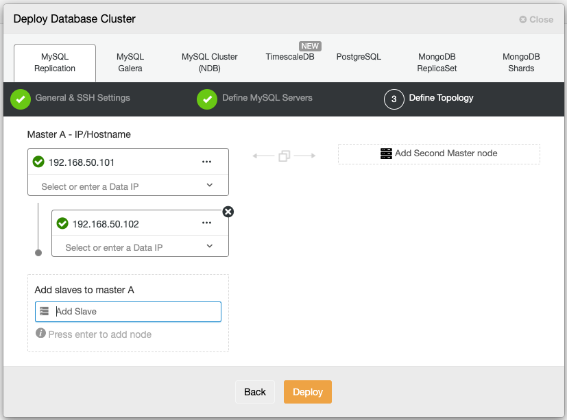
Click Deploy and wait until the deployment is complete. Once done, you should see the following:
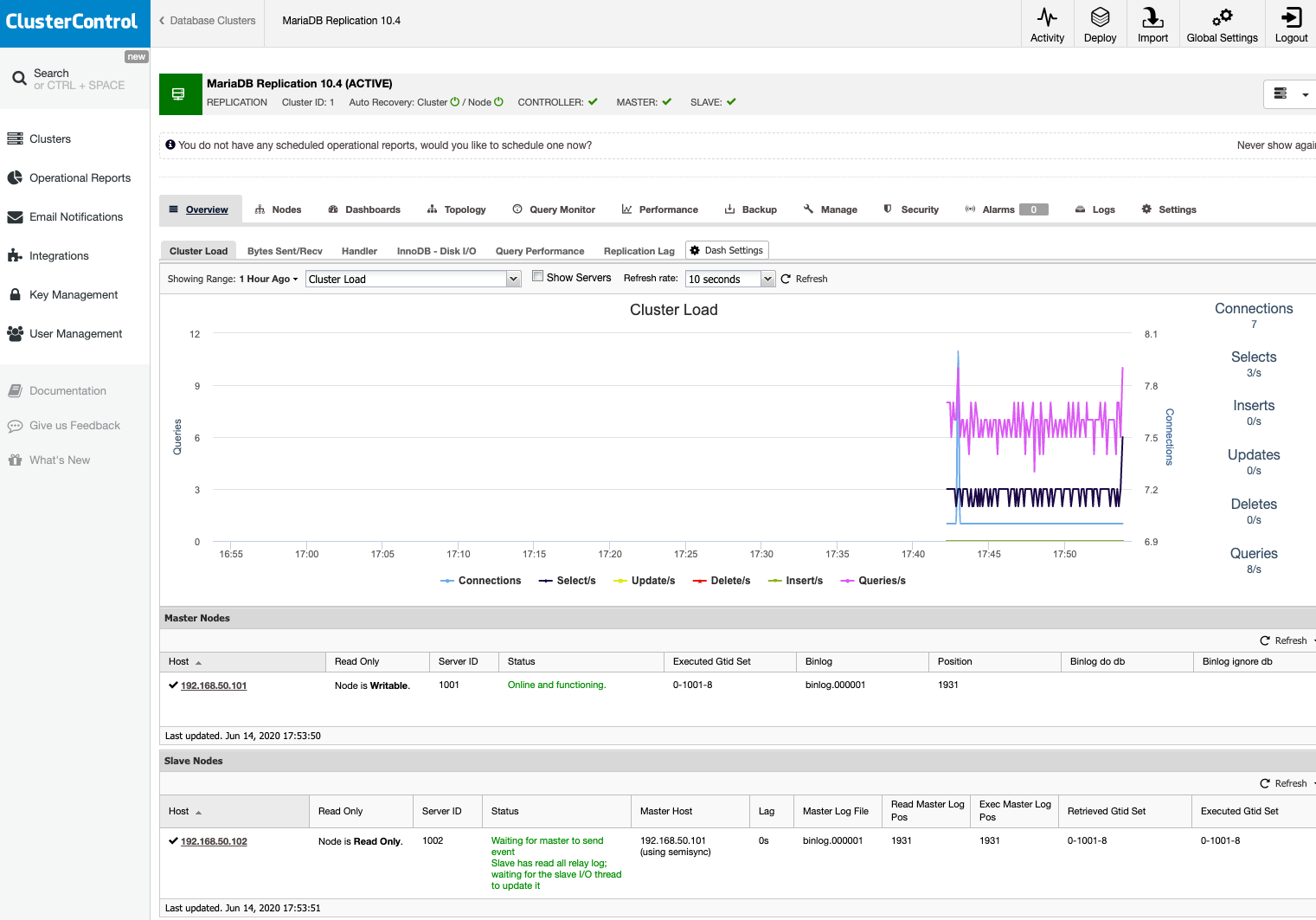
Our MariaDB replication setup is now running on three different locations (office, AWS and GCP), connected with a secure VPN tunneling between nodes.