blog
Deploying Secure Multicloud MySQL Replication on AWS and GCP with VPN

Why Choose MySQL Replication?
Some basics first about the replication technology. MySQL Replication is not complicated! It is easy to implement, monitor, and tune as there are various resources you can leverage – google being one. MySQL Replication does not contain a lot of configuration variables to tune. SQL_THREAD and IO_THREAD’s logical errors aren’t that hard to understand and fix. MySQL Replication is very popular nowadays and offers a simple way of implementing database High Availability. Powerful features such as GTID (Global Transaction Identifier) instead of the old-fashioned binary log position, or lossless Semi-Synchronous Replication make it more robust.
As we saw in an earlier post, network latency is a big challenge when selecting a high availability solution. Using MySQL Replication offers the advantage of not being as sensitive to latency. It does not implement any certification-based replication, unlike Galera Cluster uses group communication and transaction ordering techniques to achieve synchronous replication. Thus, it has no requirement that all of the nodes have to certify a writeset, and no need to wait before a commit on the other slave or replica.
Choosing the traditional MySQL Replication with asynchronous Primary-Secondary approach provides you speed when it comes to handling transactions from within your master; it does not need to wait for the slaves to sync or commit transactions. The setup typically has a primary (master) and one or more secondaries (slaves). Hence, it is a shared-nothing system, where all servers have a full copy of the data by default. Of course there are drawbacks. Data integrity can be an issue if your slaves failed to replicate due to SQL and I/O thread errors, or crashes. Alternatively, to address issues of data integrity, you can choose to implement MySQL Replication being semi-synchronous (or called lossless semi-sync replication in MySQL 5.7). How this works is that, the master has to wait until a replica acknowledges all events of the transaction. This means that it has to finish its writes to a relay log and flush to disk before it sends back to the master with an ACK response. With semi-synchronous replication enabled, threads or sessions in the master has to wait for acknowledgement from a replica. Once it gets an ACK response from the replica, it can then commit the transaction. The illustration below shows how MySQL handles semi-synchronous replication.
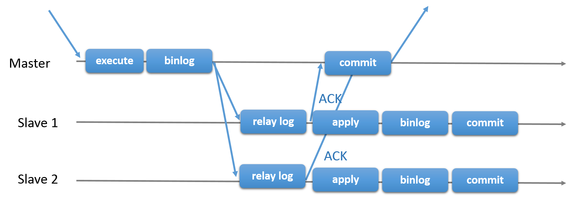
With this implementation, all committed transaction are already replicated to at least one slave in case of a master crash. Although semi-synchronous does not represent by itself a high-availability solution, but it’s a component for your solution. It’s best that you should know your needs and tune your semi-sync implementation accordingly. Hence, if some data loss is acceptable, then you can instead use the traditional asynchronous replication.
GTID-based replication is helpful to the DBA as it simplifies the task to do a failover, especially when a slave is pointed to another master or new master. This means that with a simple MASTER_AUTO_POSITION=1 after setting the correct host and replication credentials, it will start replicating from the master without the need to find and specify the correct binary log x & y positions. Adding support of parallel replication also boosts the replication threads as it adds speed to process the events from the relay log.
Thus, MySQL Replication is a great choice component over other HA solutions if it suits your needs.
Topologies for MySQL Replication
Deploying MySQL Replication in a multicloud environment with GCP (Google Cloud Platform) and AWS is still the same approach if you have to replicate on-prem.
There are various topologies you can setup and implement.
Master with Slave Replication (Single Replication)
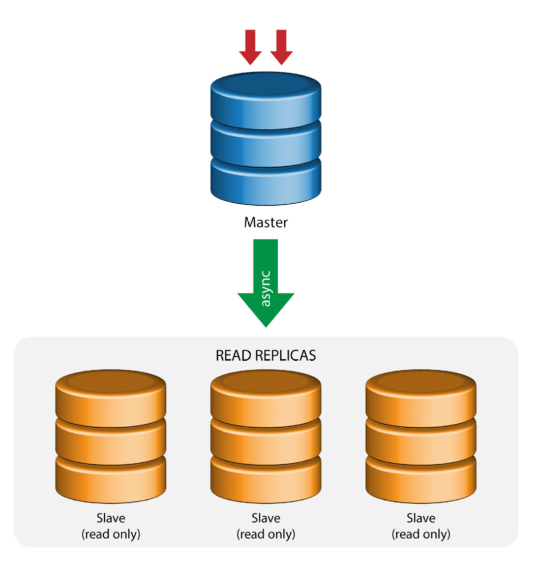
This the most straightforward MySQL replication topology. One master receives writes, one or more slaves replicate from the same master via asynchronous or semi- synchronous replication. If the designated master goes down, the most up-to-date slave must be promoted as new master. The remaining slaves resume the replication from the new master.
Master with Relay Slaves (Chain Replication)
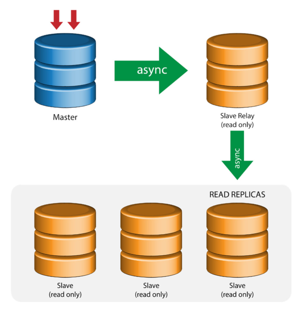
This setup use an intermediate master to act as a relay to the other slaves in the replication chain. When there are many slaves connected to a master, the network interface of the master can get overloaded. This topology allows the read replicas to pull the replication stream from the relay server to offload the master server. On the slave relay server, binary logging and log_slave_updates must be enabled, whereby updates received by the slave server from the master server are logged to the slave’s own binary log.
Using slave relay has its problems:
- log_slave_updates has some performance penalty.
- Replication lag on the slave relay server will generate delay on all of its slaves.
- Rogue transactions on the slave relay server will infect of all its slaves.
- If a slave relay server fails and you are not using GTID, all of its slaves stop replicating and they need to be reinitialized.
Master with Active Master (Circular Replication)
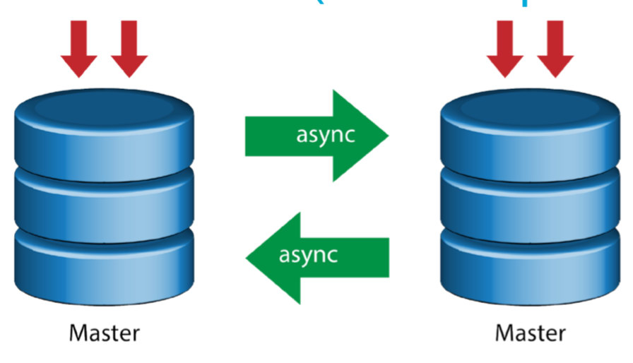
Also known as ring topology, this setup requires two or more MySQL servers which act as master. All masters receive writes and generate binlogs with a few caveats:
- You need to set auto-increment offset on each server to avoid primary key collisions.
- There is no conflict resolution.
- MySQL Replication currently does not support any locking protocol between master and slave to guarantee the atomicity of a distributed update across two different servers.
- Common practice is to only write to one master and the other master acts as a hot-standby node. Still, if you have slaves below that tier, you have to switch to the new master manually if the designated master fails.
- ClusterControl does support this topology (we do not recommend multiple writers in a replication setup). See this previous blog on how to deploy with ClusterControl.
Master with Backup Master (Multiple Replication)
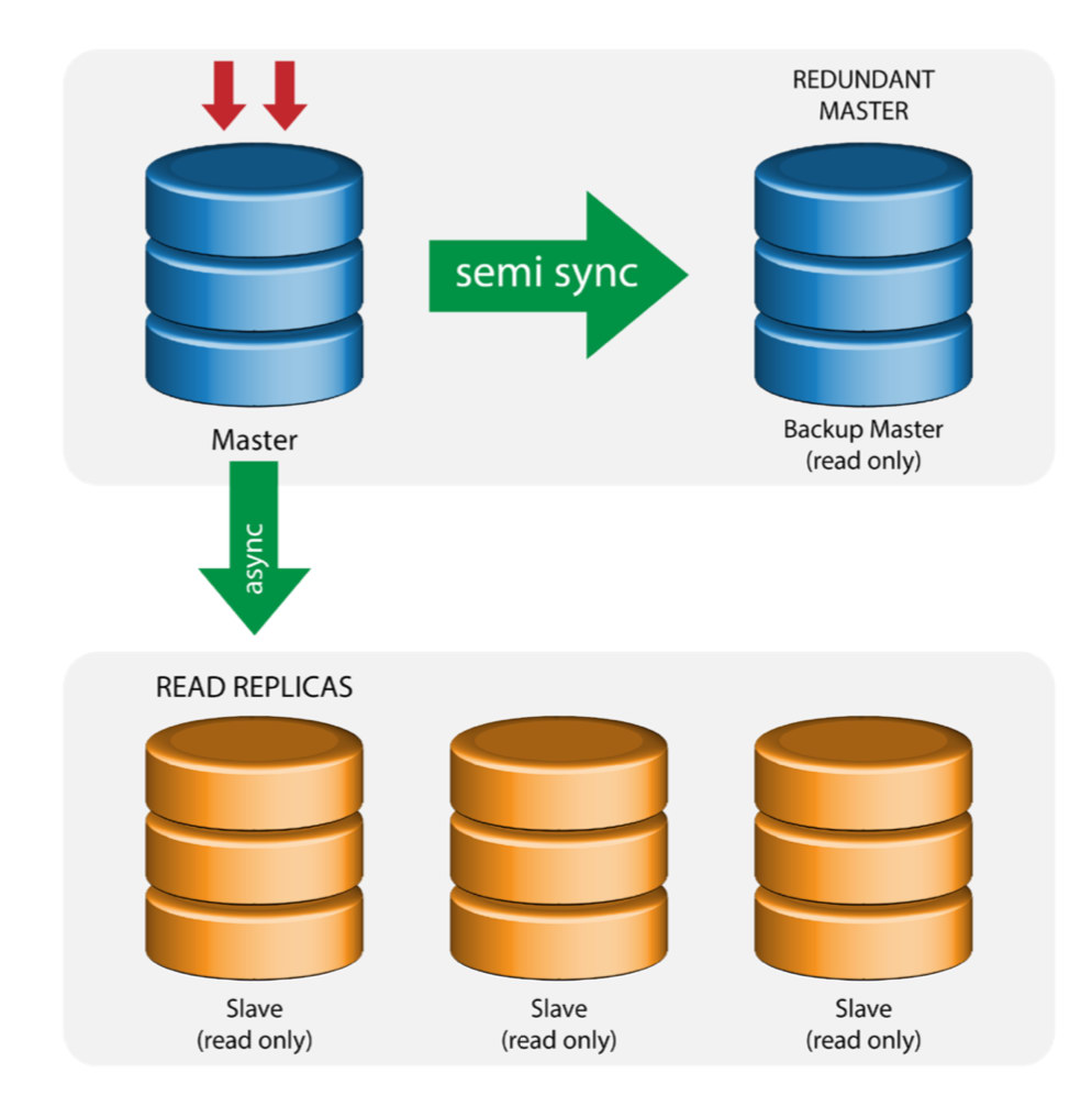
The master pushes changes to a backup master and to one or more slaves. Semi-synchronous replication is used between master and backup master. Master sends update to backup master and waits with transaction commit. Backup master gets updates, writes to its relay log and flushes to disk. Backup master then acknowledges receipt of the transaction to the master, and proceeds with transaction commit. Semi- sync replication has a performance impact, but the risk for data loss is minimized.
This topology works well when performing master failover in case the master goes down. The backup master acts as a warm-standby server as it has the highest probability of having up-to-date data when compared to other slaves.
Multiple Masters to Single Slave (Multi-Source Replication)
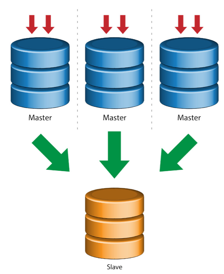
Multi-Source Replication enables a replication slave to receive transactions from multiple sources simultaneously. Multi-source replication can be used to backup multiple servers to a single server, to merge table shards, and consolidate data from multiple servers to a single server.
MySQL and MariaDB have different implementations of multi-source replication, where MariaDB must have GTID with gtid-domain-id configured to distinguish the originating transactions while MySQL uses a separate replication channel for each master the slave replicates from. In MySQL, masters in a multi-source replication topology can be configured to use either global transaction identifier (GTID) based replication, or binary log position-based replication.
More on MariaDB multi source replication can be found in this blog post. For MySQL, please refer to the MySQL documentation.
Galera with Replication Slave (Hybrid Replication)
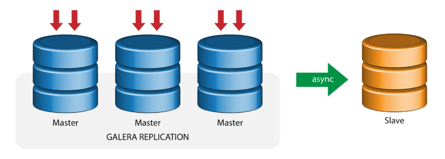
Hybrid replication is a combination of MySQL asynchronous replication and virtually synchronous replication provided by Galera. The deployment is now simplified with the implementation of GTID in MySQL replication, where setting up and performing master failover has become a straightforward process on the slave side.
Galera cluster performance is as fast as the slowest node. Having an asynchronous replication slave can minimize the impact on the cluster if you send long-running reporting/OLAP type queries to the slave, or if you perform heavy jobs that require locks like mysqldump. The slave can also serve as a live backup for onsite and offsite disaster recovery.
Hybrid replication is supported by ClusterControl and you can deploy it directly from the ClusterControl UI. For more information on how to do this, please read the blog posts – Hybrid replication with MySQL 5.6 and Hybrid replication with MariaDB 10.x.
Preparing GCP and AWS Platforms
The “real-world” Problem
In this blog, we will demonstrate and use the “Multiple Replication” topology in which instances on two different public cloud platforms will communicate using MySQL Replication on different regions and on different availability zones. This scenario is based on a real-world problem where an organization wants to architect their infrastructure on multiple cloud platforms for scalability, redundancy, resiliency/fault-tolerance. Similar concepts would apply for MongoDB or PostgreSQL.
Let’s consider a US organization, with an overseas branch in south east Asia. Our traffic is high within the Asian-based region. Latency must be low when catering for writes and reads, but at the same time the US-based region can also pull-up records coming from the Asian-based traffic.
The Cloud Architecture Flow
In this section, I will discuss the architectural design. First, we want to offer a highly-secure layer for which our Google Compute and AWS EC2 nodes can communicate, update or install packages from the internet, secure, highly-available in case an AZ (Availability Zone) goes down, can replicate and communicate to another cloud platform over a secured layer. See the image below for illustration:
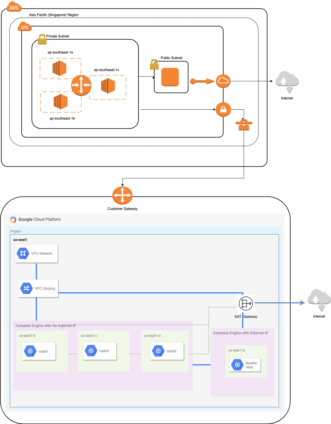
Based on the illustration above, under the AWS platform, all nodes are running on different availability zones. It has a private and public subnet for which all the compute nodes are on a private subnet. Hence, it can go outside the internet to pull and update its system packages when needed. It has a VPN gateway for which it has to interact with GCP in that channel, bypassing the Internet but through a secure and private channel. Same as GCP, all compute nodes are on different availability zones, use NAT Gateway to update system packages when needed and use VPN connection to interact with the AWS nodes which are hosted on a different region, i.e. Asia Pacific (Singapore). On the other hand, the US-based region is hosted under us-east1. In order to access the nodes, one node in the architecture serves as the bastion-node for which we will use it as the jump host and install ClusterControl. This will be tackled later in this blog.
Setting up GCP and AWS Environments
When registering your first GCP account, Google provides a default VPC (Virtual Private Cloud) account. Hence, it’s best to create a separate VPC than the default and customize it according to your needs.
Our goal here is to place the compute nodes in private subnets or nodes will not be setup with public IPv4. Hence, both public clouds must be able to talk to each other. The AWS and GCP compute nodes operate with different CIDRs as previously mentioned. Hence, here are the following CIDR:
AWS Compute Nodes: 172.21.0.0/16
GCP Compute Nodes: 10.142.0.0/20
In this AWS setup, we allocated three subnets which has no Internet Gateway but NAT Gateway; and one subnet which has an Internet Gateway. Each of these subnets are hosted individually in different Availability Zones (AZ).
ap-southeast-1a = 172.21.1.0/24
ap-southeast-1b = 172.21.8.0/24
ap-southeast-1c = 172.21.24.0/24
While in GCP, the default subnet created in a VPC under us-east1 which is 10.142.0.0/20 CIDR is used. Hence, these are the steps you can follow to setup your multi-public cloud platform.
- For this exercise, I created a VPC in us-east1 region with the following subnet of 10.142.0.0/20. See below:

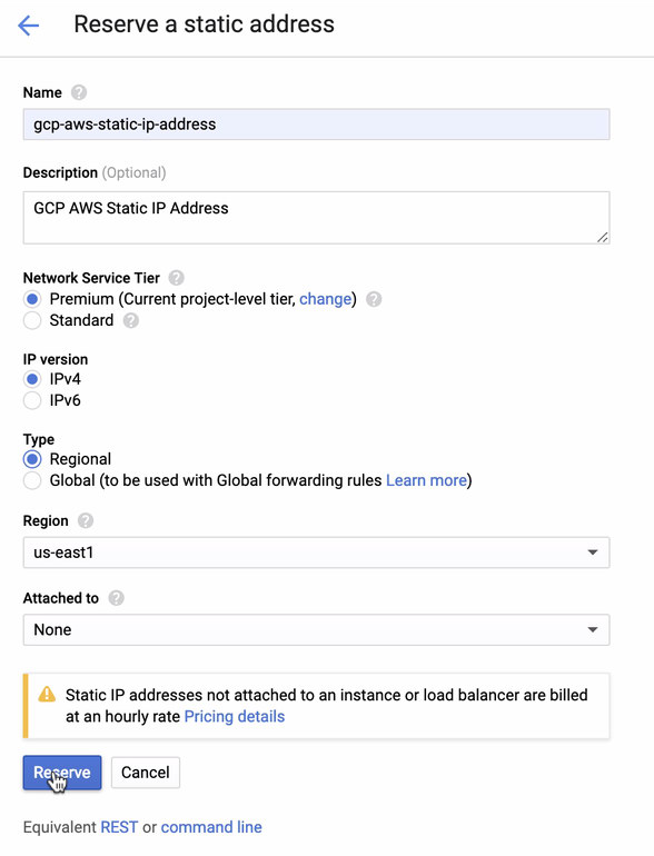
- Reserve a Static IP. This is the IP that we will be setting up as a Customer Gateway in AWS
- Since we have subnets in place (provisioned as subnet-us-east1), go to GCP -> VPC Network -> VPC Networks and select the VPC you created and go to the Firewall Rules. In this section, add the rules by specifying your ingress and egress. Basically, these are the inbound/outbound rules in AWS or your firewall for incoming and outgoing connections. In this setup, I opened all TCP protocols from the CIDR range set in my AWS and GCP VPC to make it simpler for the purpose of this blog. Hence, this is not the optimal way for security. See image below:
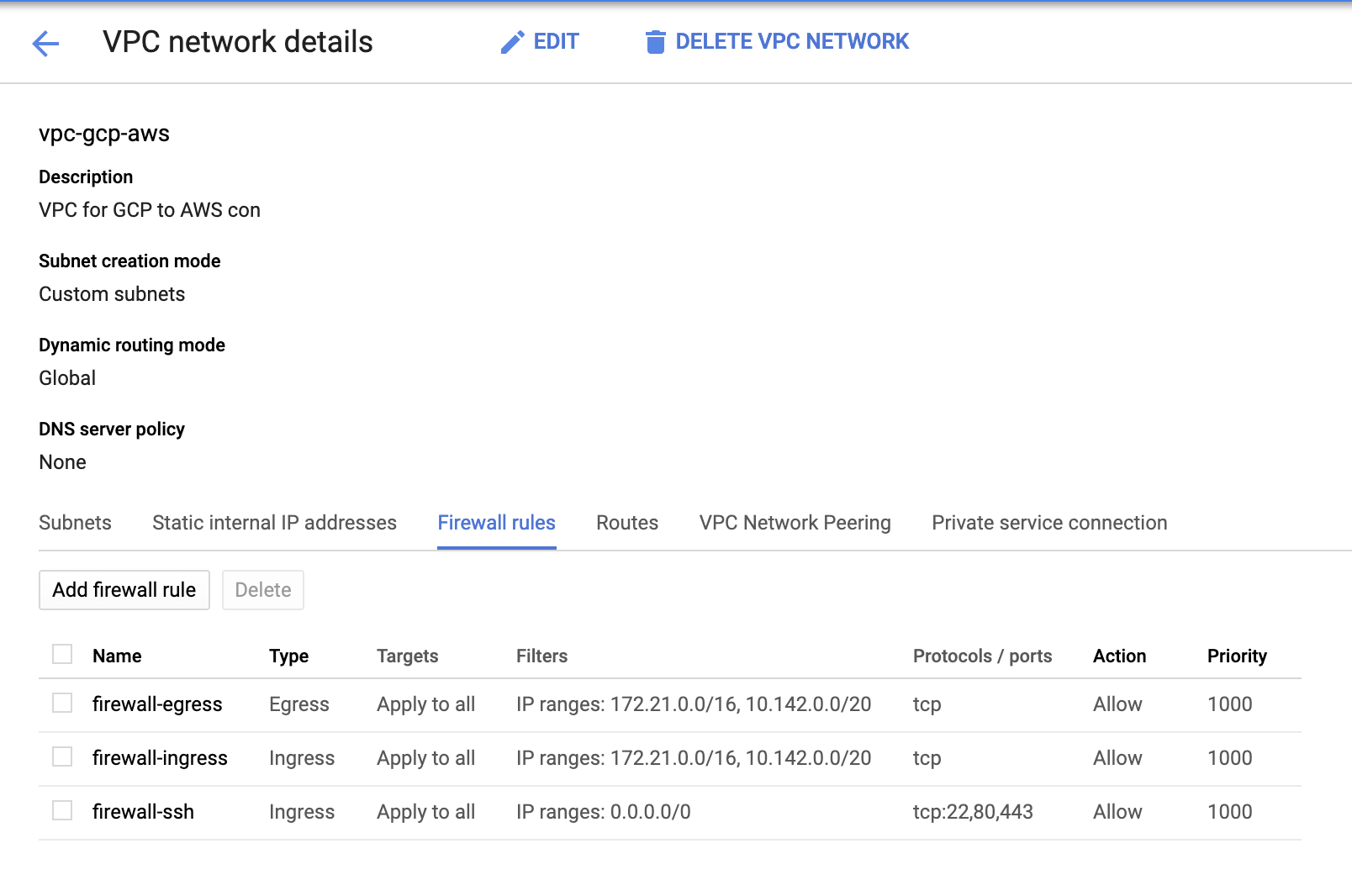
The firewall-ssh here will be used to allow ssh, HTTP and HTTPS incoming connections.
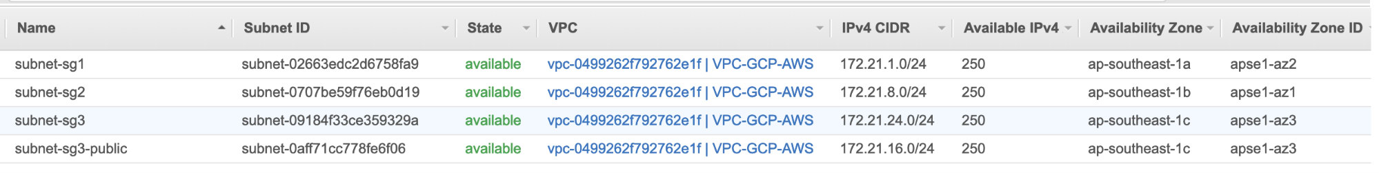
- Now switch to AWS and create a VPC. For this blog, I used CIDR (Classless Inter-Domain Routing) 172.21.0.0/16
- Create the subnets for which you have to assign them in each AZ (Availability Zone); and at least reserve one subnet for a public subnet which will handle the NAT Gateway, and the rest are for EC2 nodes.
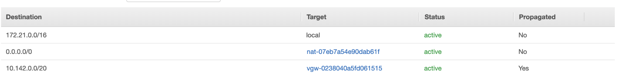
- Next, create your Route Table and ensure that the “Destination” and “Targets” are set correctly. For this blog, I created 2 route tables. One which will handle the 3 AZ which my compute nodes will be assigned individually and will be assigned without an Internet Gateway as it will have no public IP. Then the other one will handle the NAT Gateway and will have an Internet Gateway which will be in the public subnet. See image below:

and as mentioned, my example destination for private route that handles 3 subnets shows to have a NAT Gateway target plus a Virtual Gateway target which I will mention later in the incoming steps.
- Next, create an “Internet Gateway” and assign it to the VPC that was previously created in the AWS VPC section. This Internet Gateway shall only be set as destination to the public subnet as it will be the service that has to connect to the internet. Obviously, the name stands for as an internet gateway service.
- Next, create a “NAT Gateway”. When creating a “NAT Gateway”, ensure that you have assigned your NAT to a public-facing subnet. The NAT Gateway is your channel to access the internet from your private subnet or EC2 nodes that have no public IPv4 assigned. Then create or assign an EIP (Elastic IP) since, in AWS, only compute nodes that have public IPv4 assigned can connect to the internet directly.
- Now, under VPC -> Security -> Security Groups (SG), your created VPC will have a default SG. For this setup, I created “Inbound Rules” with sources assigned for each CIDR i.e. 10.142.0.0/20 in GCP and 172.21.0.0/16 in AWS. See below:
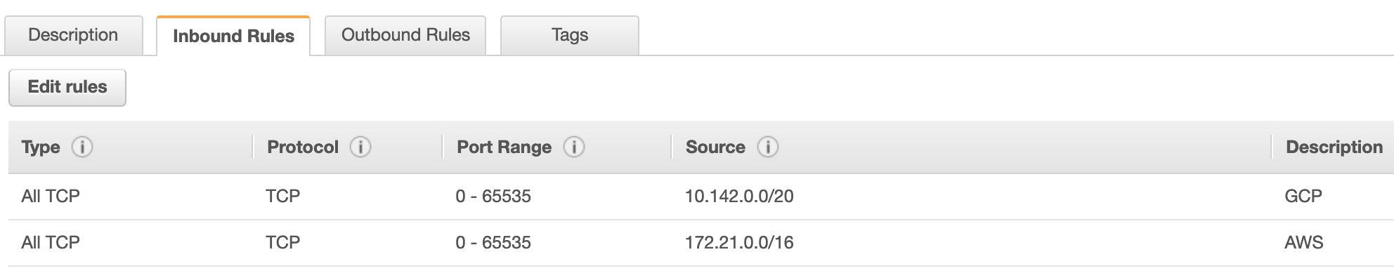
For “Outbound Rules”, you can leave that as is since assigning rules to “Inbound Rules” is bilateral, which means it’ll open as well for “Outbound Rules”. Take note that this is not the optimal way for setting your Security Group; but to make it easier for this setup, I have made a wider scope of port range and source as well. Also that the protocol are specific for TCP connections only since we’ll not be dealing with UDP for this blog.
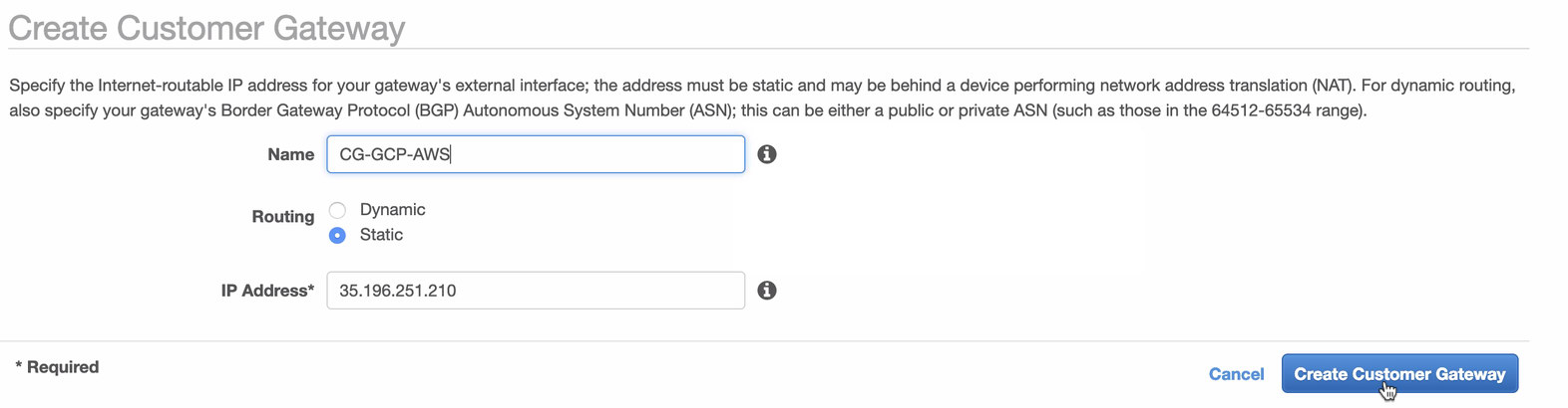
Additionally, you can leave your VPC -> Security -> Network ACLs untouched as long as it does not DENY any tcp connections from the CIDR stated in your source. - Next, we’ll setup the VPN configuration which will be hosted under AWS platform. Under the VPC -> Customer Gateways, create the gateway using the static IP address that were created earlier in the previous step. Take a look at the image below:
- Next, create a Virtual Private Gateway and attach this to the current VPC that we created previously in the previous step. See image below:

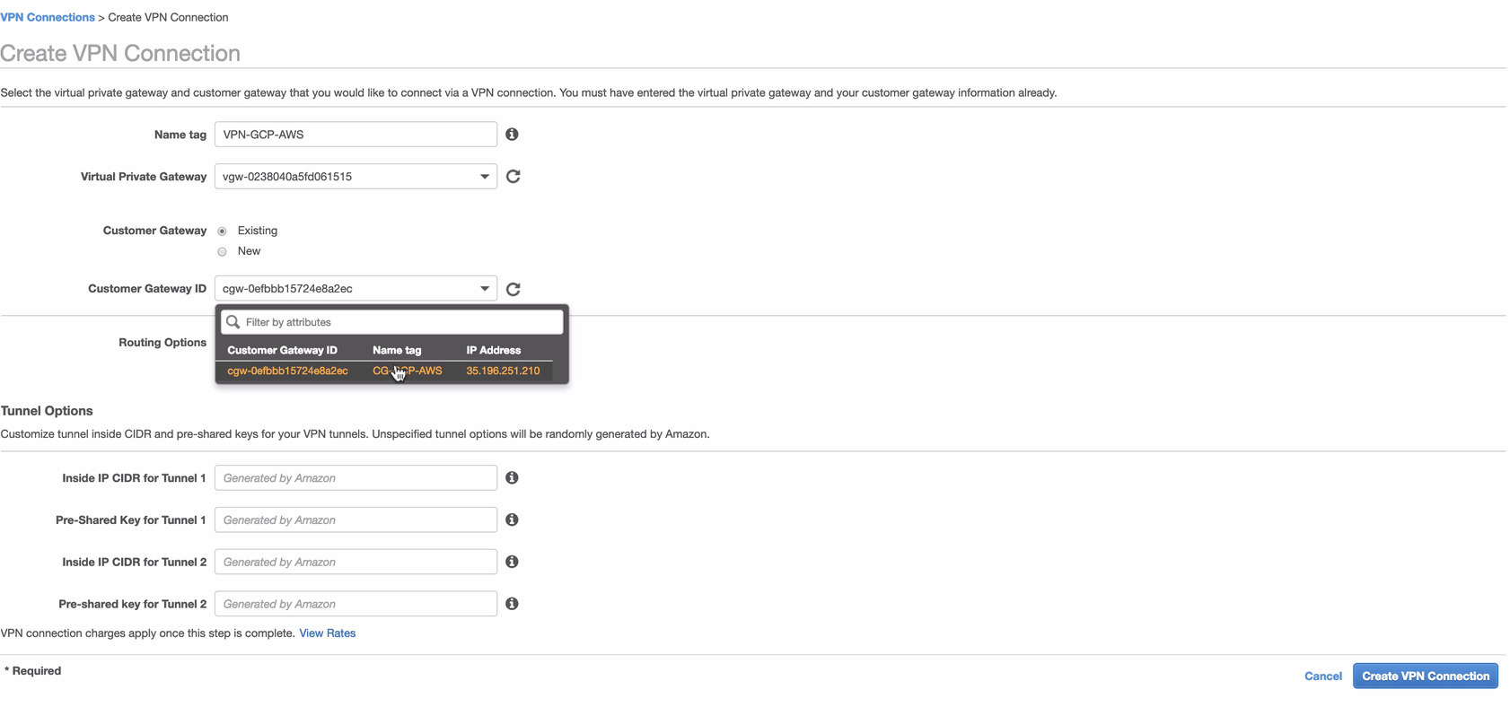
- Now, create a VPN connection which will be used for the site-to-site connection between AWS and GCP. When creating a VPN connection, make sure that you have selected the correct Virtual Private Gateway and the Customer Gateway that we created in the previous steps. See image below:
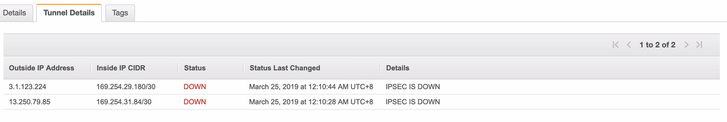
This might take some time while AWS is creating your VPN connection. When your VPN connection is then provisioned, you might wonder why under the Tunnel tab (after you select your VPN connection), it will show that the Outside IP Address is down. This is normal as there’s no connection that has been established yet from the client. Take a look at the example image below:
Once the VPN connection is ready, select your VPN connection created and download the configuration. It contains your credentials needed for the following steps to create a site-to-site VPN connection with the client.
Note: In case you have setup your VPN where IPSEC IS UP but Status is DOWN just like the image below

this is likely due to wrong values set to the specific parameters while setting up your BGP session or cloud router. Check it out here for troubleshooting your VPN.
- Since we have a VPN connection ready hosted in AWS, let’s create a VPN connection in GCP. Now, let’s go back to GCP and setup the client connection there. In GCP, go to GCP -> Hybrid Connectivity -> VPN. Make sure that you are choosing the correct region, which is on this blog, we’re using us-east1. Then select the static IP address created in the previous steps. See image below:
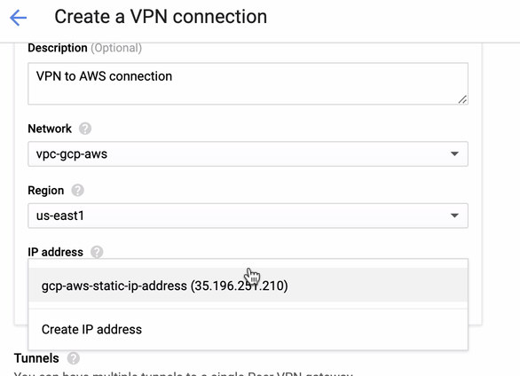
Then in the Tunnels section, this is where you’ll have to setup based on the downloaded credentials from the AWS VPN connection you created previously. I suggest to check out this helpful guide from Google. For example, one of the tunnels being setup is shown in the image below:
Basically, the most important things here are the following:
- Remote Peer Gateway: IP Address – This is the IP of the VPN server stated under the Tunnel Details -> Outside IP Address. This is not to be confused of the static IP we created under GCP. That is the Cloud VPN gateway -> IP address though.
- Cloud router ASN – By default, AWS uses 65000. But likely, you’ll get this information from the downloaded configuration file.
- Peer router ASN – This is the Virtual Private Gateway ASN which is found in the downloaded configuration file.
- Cloud Router BGP IP address – This is the Customer Gateway found in the downloaded configuration file.
- BGP peer IP address – This is the Virtual Private Gateway found in the downloaded configuration file.
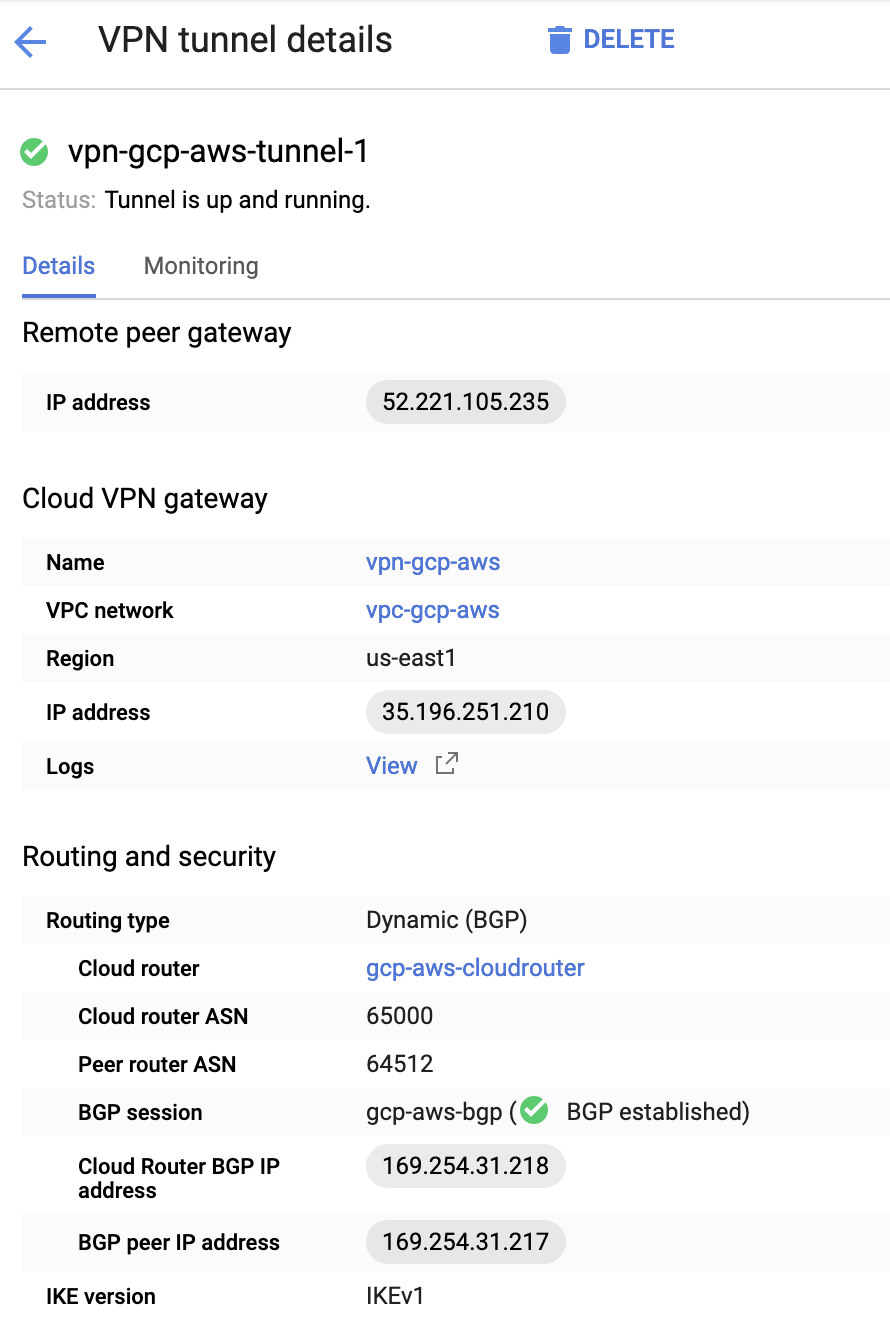
- Take a look at the example configuration file I have below:
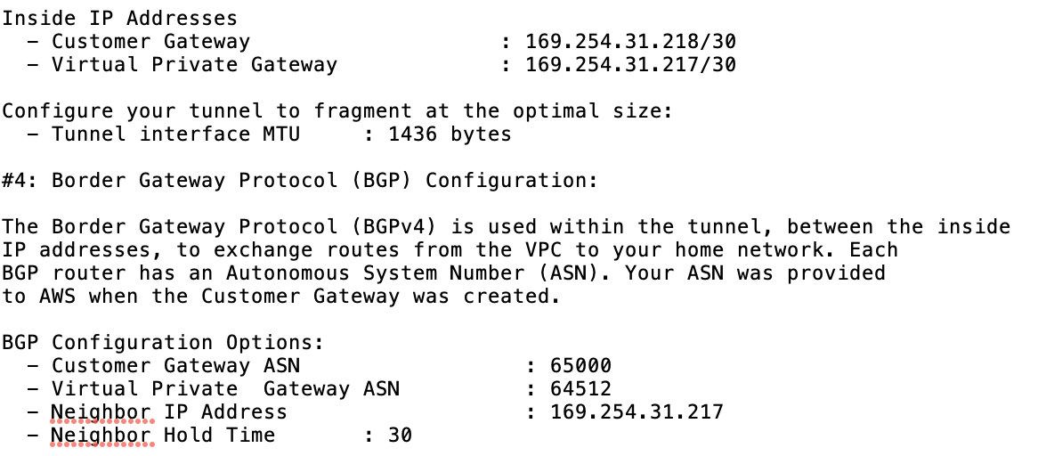
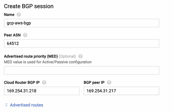
for which you have to match this during adding your Tunnel under the GCP -> Hybrid Connectivity -> VPN connectivity setup. See the image below for which I created a cloud router and a BGP session during creating a sample tunnel:
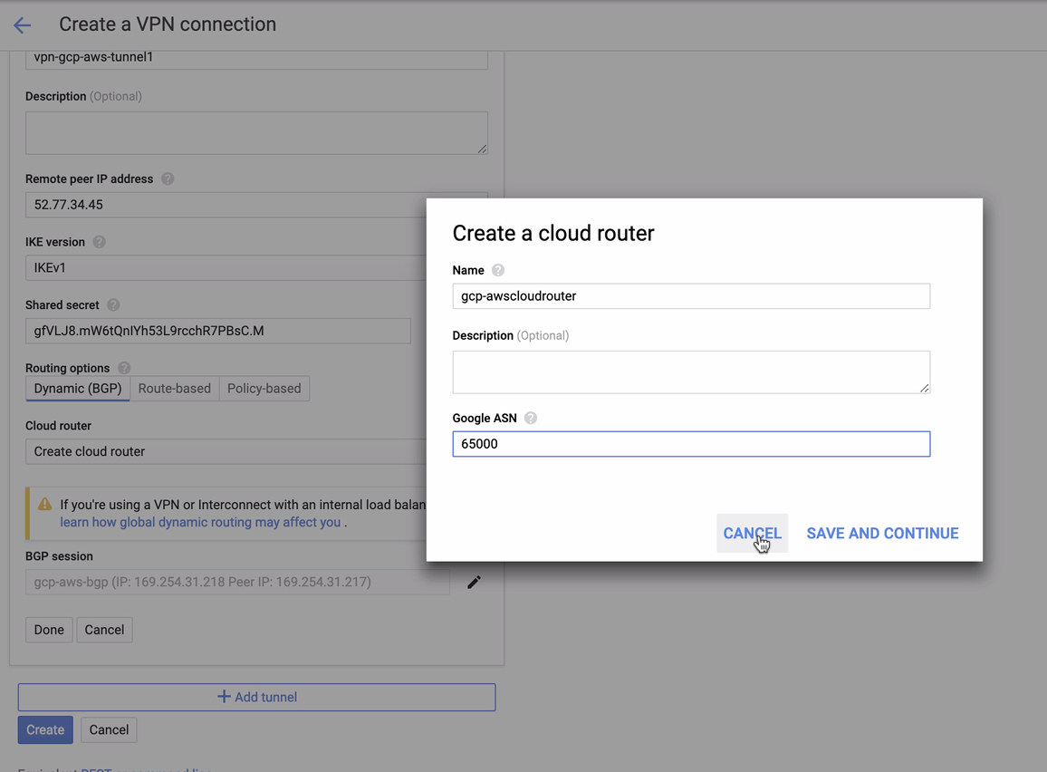
Then BGP session as,

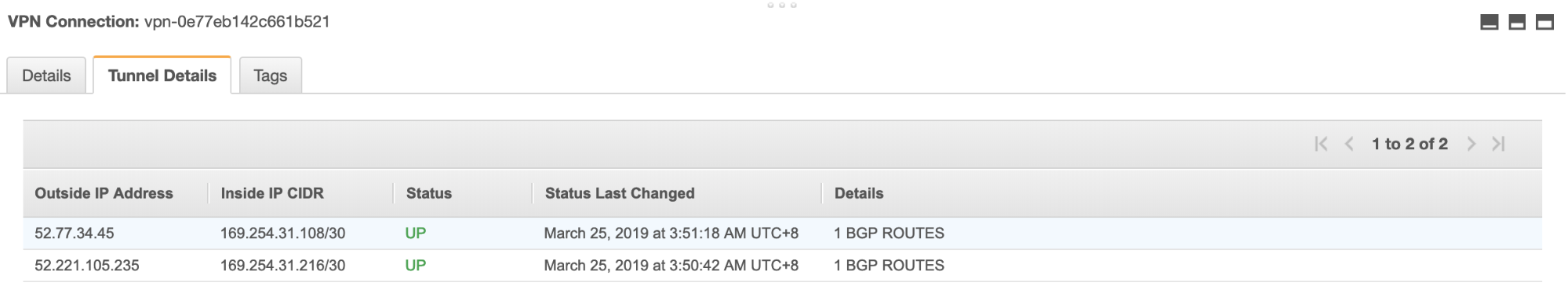
Note: The downloaded configuration file contains IPSec configuration tunnel for which AWS as well contains two (2) VPN servers ready for your connection. You must have to setup both of them so that you’ll have a high available setup. Once its setup for both tunnels correctly, the AWS VPN connection under the Tunnels tab will show that both Outside IP Address are up. See image below:
- Lastly, since we have created an Internet Gateway and NAT Gateway, populate the public and private subnets correctly with correct Destination and Target as noticed in the screenshot from previous steps. This can be setup by going to Services -> Networking & Content Delivery -> VPC -> Route Tables and select the created route tables mentioned from the previous steps. See the image below:
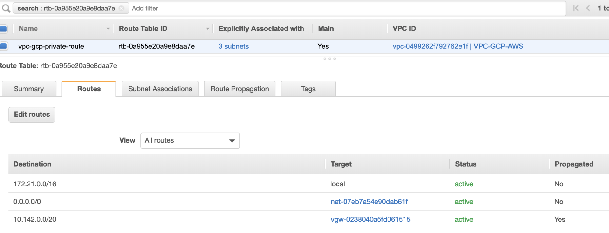
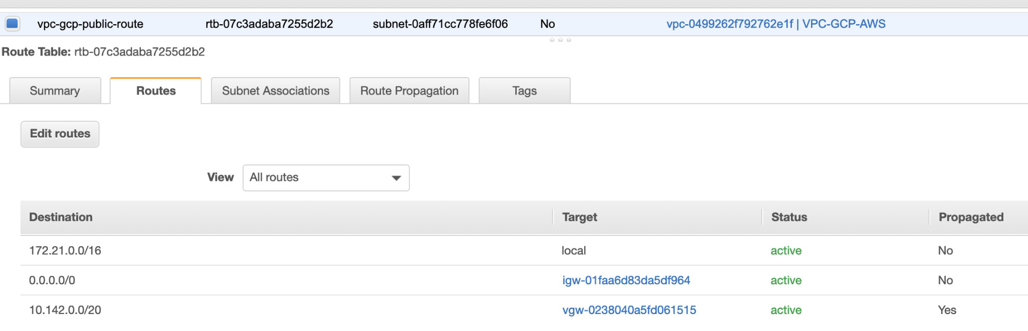
As you noticed, the igw-01faa6d83da5df964 is the Internet Gateway that we created and is used by the public route. Whilst, the private route table has destination and target set to nat-07eb7a54e90dab61f and both of these have Destination set to 0.0.0.0/0 since it’ll allow from different IPv4 connections. Also do not forget to set the Route Propagation correctly for the Virtual Gateway as seen in the screenshot which has a target vgw-0238040a5fd061515. Just click Route Propagation and set it to Yes just like in the screenshot below:
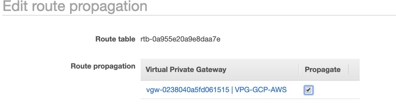
This is very important so that the connection from the external GCP connections will route to the route tables in AWS and no further manual work needed. Otherwise, your GCP cannot establish connection to AWS.
Now that our VPN is up, we’ll continue setting up our private nodes including the bastion host.
Setting up the Compute Engine Nodes
Setting up the Compute Engine/EC2 nodes will be fast and easy since we have all setup in place. I’ll not go into that details but checkout the screenshots below as it explains the setup.
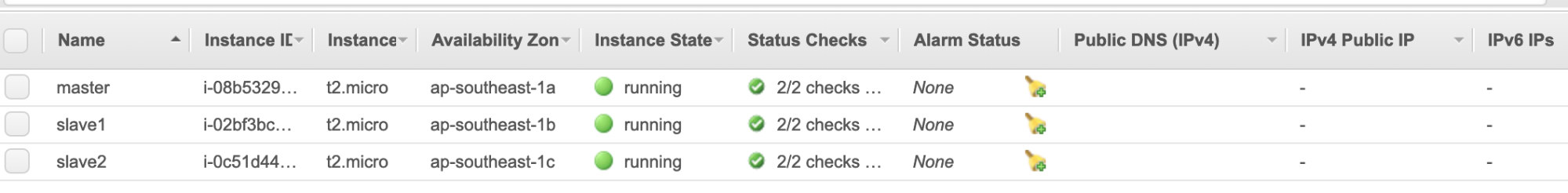
AWS EC2 Nodes:
GCP Compute Nodes:
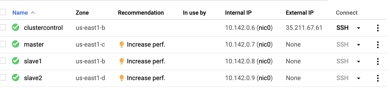
Basically, on this setup. The host clustercontrol will be the bastion or jump host and for which the ClusterControl will be installed. Obviously, all the nodes here are not internet accessible. They have no External IPv4 assigned and nodes are communicating through a very secure channel using VPN.
Lastly, all these nodes from AWS to GCP are setup with one uniform system user with sudo access, which is needed in our next section. See how ClusterControl can make your life easier when in multicloud and multi-region.
ClusterControl To The Rescue!!!
Handling multiple nodes and on different public cloud platforms, plus on a different “Region” can be a “truly-painful-and-daunting” task. How do you monitor that effectively? ClusterControl acts not only as your swiss-knife, but also as your Virtual DBA. Now, let’s see how ClusterControl can make your life easier.
Creating a Multiple-Replication Cluster using ClusterControl
Now let’s try to create a MariaDB master-slave replication cluster following the “Multiple Replication” topology.
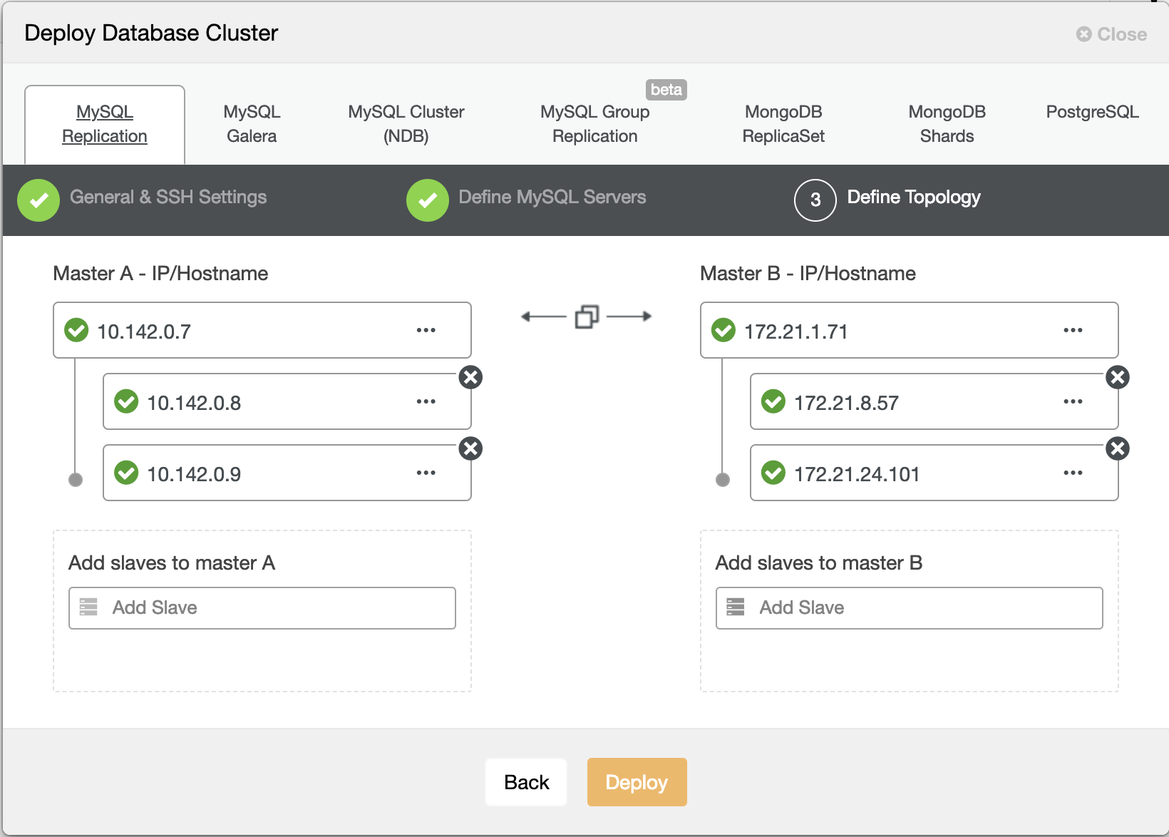
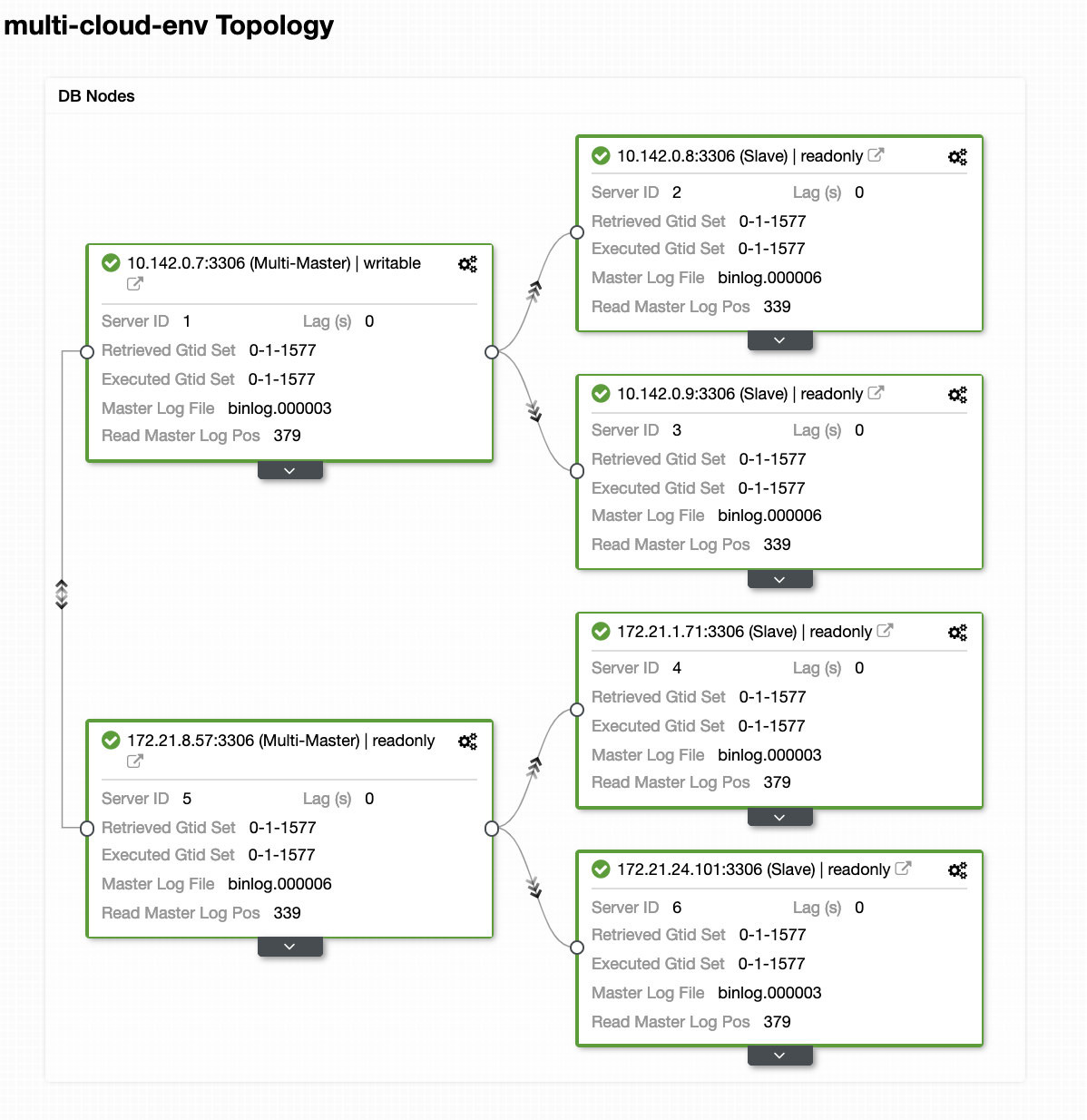
Hitting Deploy button will install packages and setup the nodes accordingly. Hence, a logical view of how the topology would look like:
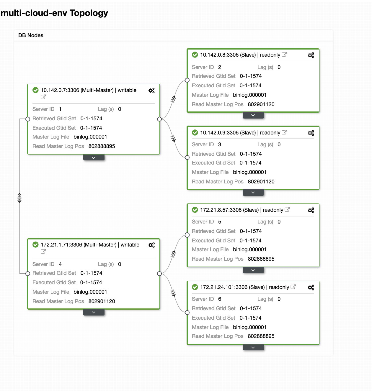
The nodes 172.21.0.0/16 range IP’s are replicating from it’s master running on GCP.
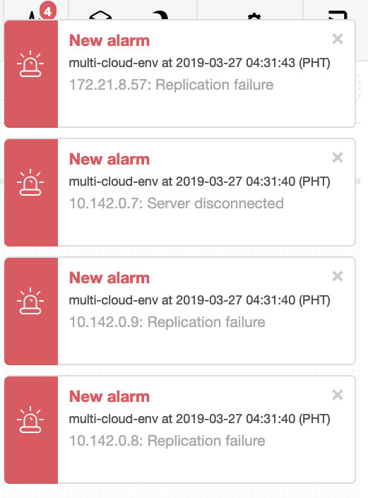
Now, how about we try to load some writes on the master? Any issues with connectivity or latency might generate slave lag, you will be able to spot this with ClusterControl. See the screenshot below:
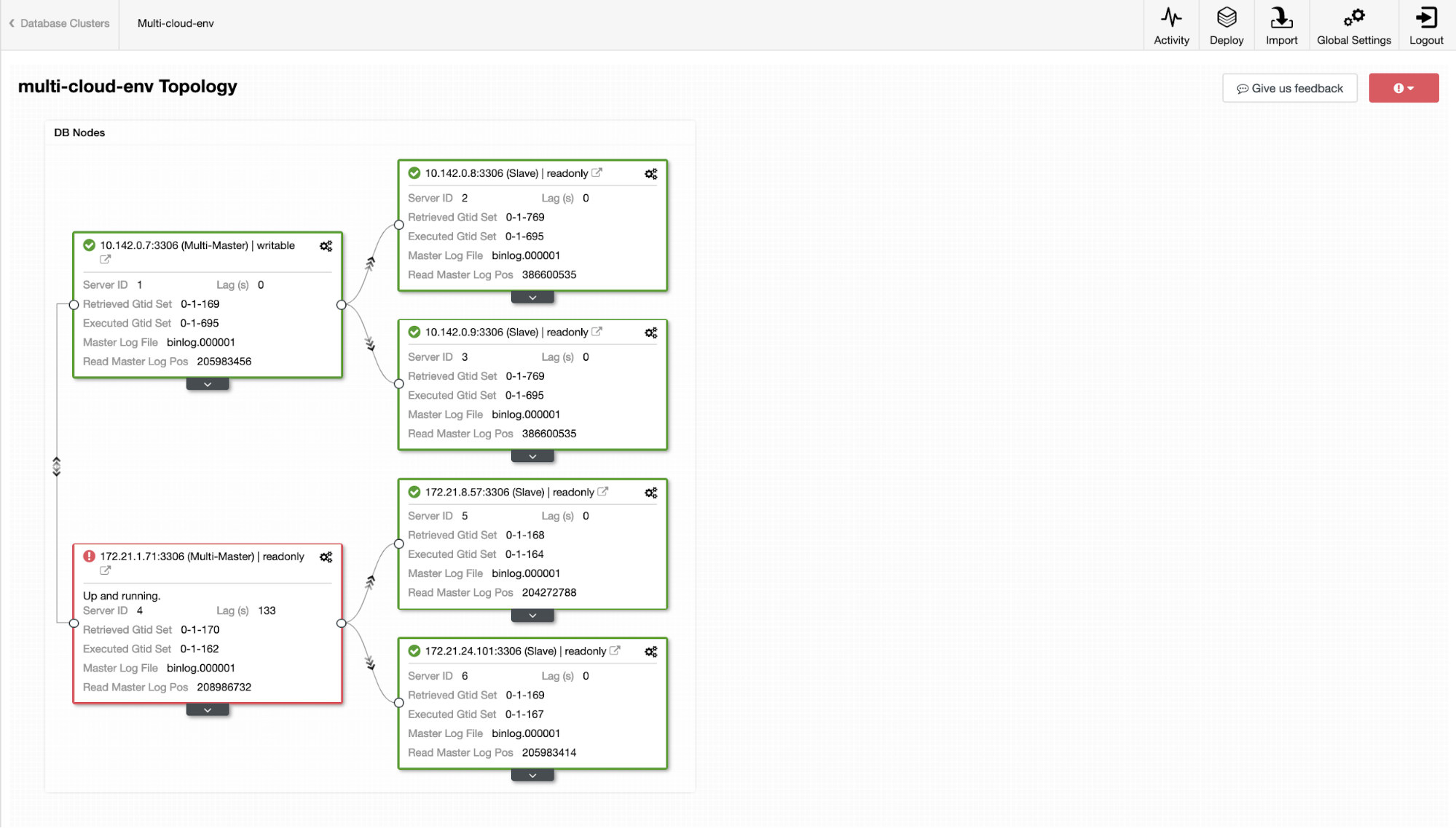
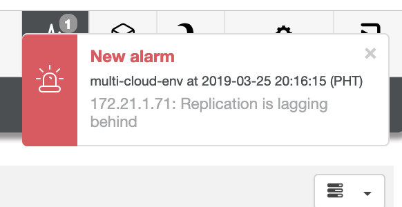
and as you see in the top-right corner of the screenshot, it turns red as it indicates issues were detected. Hence, an alarm was being sent while this issue has been detected. See below:
We need to dig into this. For fine-grained monitoring, we have enabled agents on the database instances. Let’s have a look at the Dashboard.
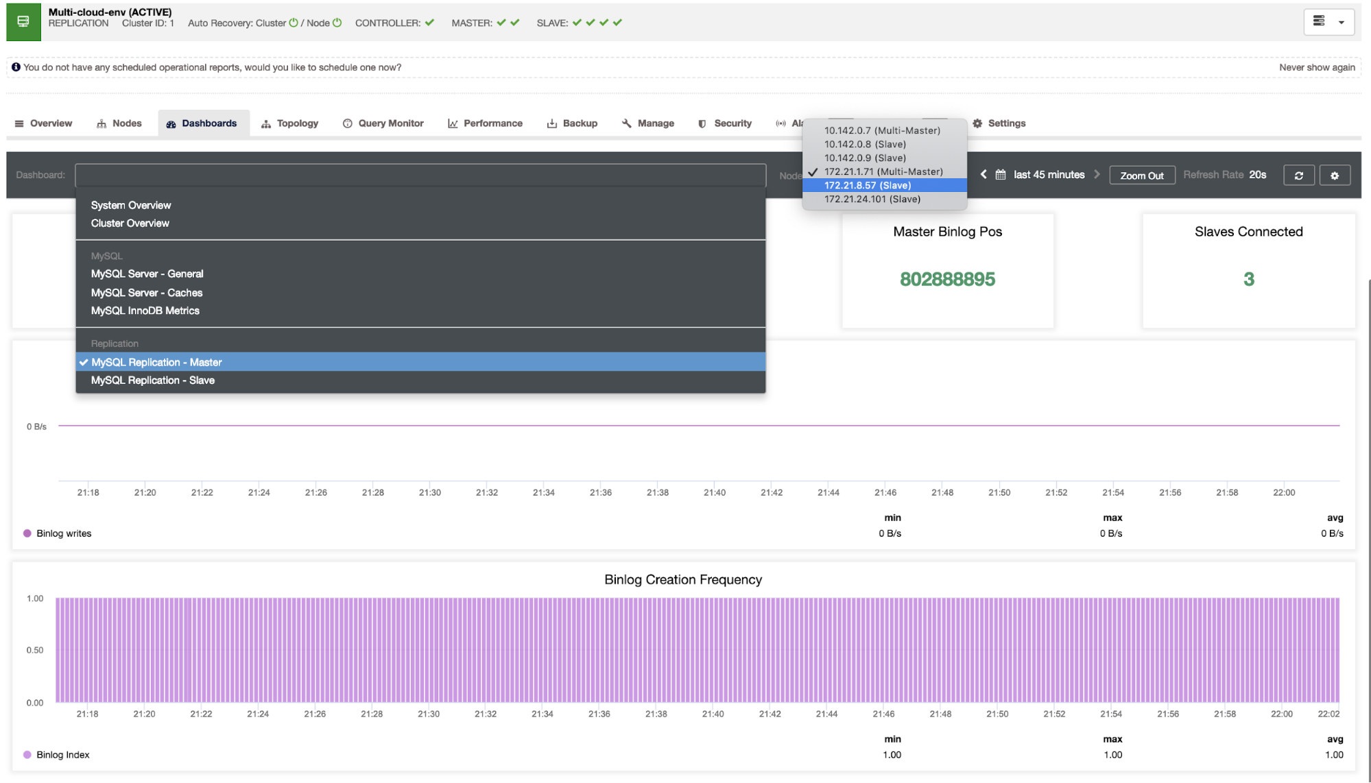
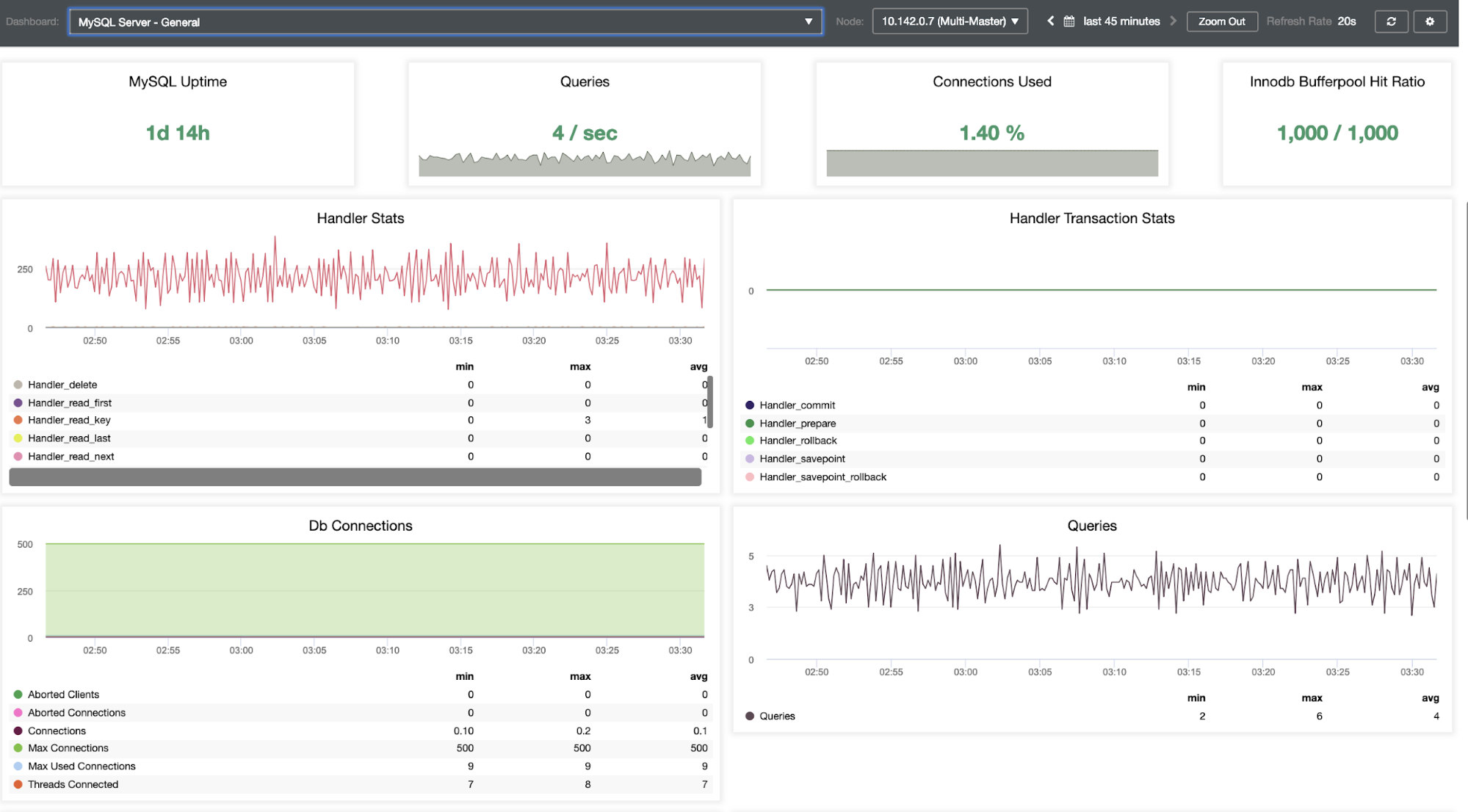
It offers a super smooth experience in terms of monitoring your nodes.
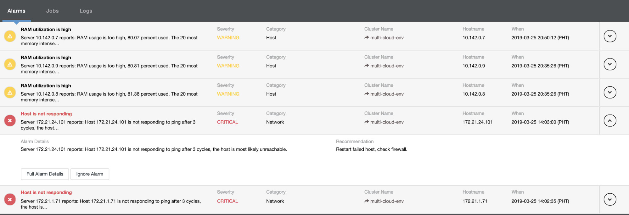
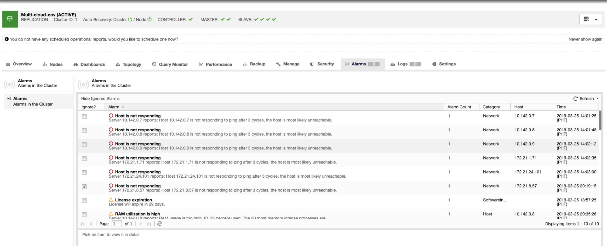
It tells us that utilization is high or host is not responding. Although this was just a ping response failure, you can ignore the alert to stop you from bombarding it. Hence, you can ‘un-ignore’ it if needed by going to Cluster -> Alarms in the Clustercontrol. See below:
Managing Failures and Performing Failover
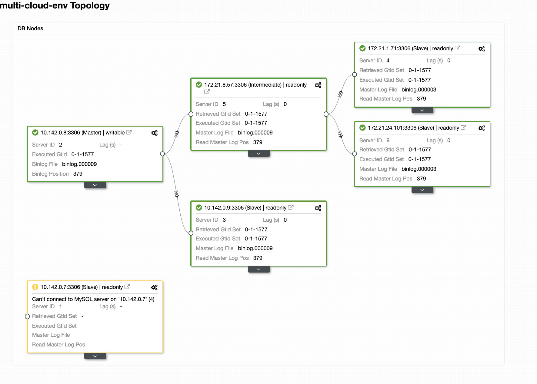
Let’s say that the us-east1 master node failed, or requires a major overhaul because of system or hardware upgrade. Let’s say this is the topology right now (see image below):
Let’s try to shutdown host 10.142.0.7 which is the master under the region us-east1. See the screenshots below how ClusterControl reacts to this:
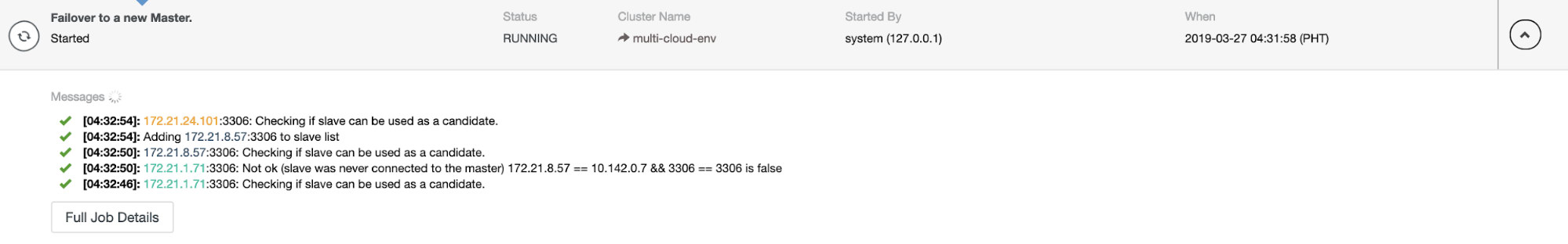
ClusterControl sends alarms once it detects anomalies in the cluster. Then it tries to do a failover to a new master by choosing the right candidate (see image below):
Then, it set aside the failed master which has been already taken out from the cluster (see image below):
This is just a glimpse of what ClusterControl can do, there are other great features such as backups, query monitoring, deploying/managing load balancers, and many more!
Conclusion
Managing your MySQL Replication setup in a multicloud can be tricky. Much care must be taken to secure our setup, so hopefully this blog gives an idea on how to define subnets and protect the database nodes. After security, there are a number of things to manage and this is where ClusterControl can be very helpful.
Try it now and do let us know how it goes. You can contact us here anytime.